

Last Friday I was disappointed to see a red light illuminate on my instrument cluster, along with an "F1" indication where the coolant temperature is displayed. The bike has a user diagnostic mode which can be activated by the following procedure:
1) Remove the seat and rear frame cover (rear fairing)
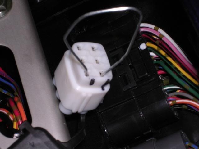
2) Find the 6-pin connector with a white, rubber cover near the relays
3) Start the bike (or turn the key to the accessory position if the bike will not start)
4) Jump the two terminals as shown in the picture below
5) Write down the error code as displayed in the coolant temperature display (WRITE IT DOWN, the code may not always remain stored after retrieval).
![Image]()
In my case, the code that came up was C-28, or Secondary Throttle Valve Actuator (SVTA). After testing the actuator per the shop manual, I concluded that the actuator was defective.
The first thing I did was call the Suzuki dealership, who told me that this part was ONLY available as a full-throttle body assembly - $800. No doubt this infuriated me. Why do I need a whole throttle body assembly for one electronic part?
After further investigation, I came to find out that this part failed often on the '04-'05 inline fours, due to an incredibly poor design that left solder points on the actuator motor electrical connector incredibly vulnerable to separation by means of vibration.
First and foremost, the SVTA is an emissions part. Some of the reading that I did on the matter alleged that emissions parts are to be warranted by the manufacturer for 5-10 years, but I wouldn't expect every dealer to honor that request. Some guys paid up to $2000 to have their throttle body housing replaced along with the SVTA to get the problem fixed.
I tore mine apart and fixed it myself. Here are the steps required to fix the SVTA that will not only save you boatloads of time and money but also give you the satisfaction of fixing it yourself.
Items needed:
The STVA is located on the right side of the throttle body housing.
To test:
1) Remove the seat
2) Lift & support the fuel tank
3) Remove the airbox cover
4) Turn the ignition switch on; the secondary throttle valves should cycle all the way open, then close very slightly to 95% open. If the valves close, proceed to step 5.
5) Use contact cleaner to clean the STVA connector.
6) Reconnect SVTA and repeat step 4. If the results are the same, proceed to step 7.
7) Test for resistance between the top two terminals and the bottom two terminals. Shown below as viewed while the unit is installed on the bike, from the rider position. Resistance should be approx. 7-8 ohms. If the unit tests badly, proceed to unit repair (below).
![Image]()
To repair:
1) Remove the seat
2) Lift & support the fuel tank
3) Match-mark position of the Secondary Throttle Position Sensor (if not already done so by the factory)
4) Remove the Secondary Throttle Position Sensor using the security Torx bit
5) Remove STVA (CAUTION: these screws can strip easily, so have an impact driver handy if necessary)
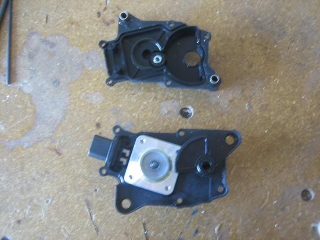
6) Drill out the rivets that hold the two halves of the STVA enclosure together
7) Carefully pull the two halves apart
![Image]()
8- Thread one of the M3 screws into the back side of the actuator motor to pull it out of the housing (rubber pads help keep the motor held in place. Removing the motor by hand may cause damage to the connecting parts)
9) Inspect the solder joints, particularly those circled in red below (those are the joints most prone to failure due to the part design).
![Image]()
10) If possible, remove all old solder from any broken joints.
11) Place motor/connector assembly into actuator housing to temporarily locate the components
12) Re-solder the four joints
13) Test the resistance between the terminal pairs as described in step 7 (testing) above.
14) Reassemble the unit, using the M3 screws in place of the original rivets (blue thread locker is recommended)
15) When facing the right side of the bike, use a flat-blade screwdriver to rotate the STVA keyway all the way counter-clockwise.
16) Install the STVA
17) Manually open the Secondary Throttle Valves (clockwise when looking at the right side of the bike)
18- Install the Secondary Throttle Position Sensor (STPS), but leave the mounting screw finger-tight
19) Manually check the operation of the Secondary Throttle Valves. If they do not open, then you have the STPS aligned improperly. Proper alignment may take several attempts, but this is an important step.
20) Align the match-marked STPS and fasten its mounting screw
21) Turn the ignition to the ON position and test as described in the testing section (At this point, your red light should no longer be illuminated if the unit has been properly repaired)
22) Install airbox cover
23) Lower & fasten the fuel tank
24) Install the seat
If you don't feel confident doing this kind of repair yourself, feel free to PM me. I'd be glad to fix it for you for a modest fee.")
1) Remove the seat and rear frame cover (rear fairing)
2) Find the 6-pin connector with a white, rubber cover near the relays
3) Start the bike (or turn the key to the accessory position if the bike will not start)
4) Jump the two terminals as shown in the picture below
5) Write down the error code as displayed in the coolant temperature display (WRITE IT DOWN, the code may not always remain stored after retrieval).
In my case, the code that came up was C-28, or Secondary Throttle Valve Actuator (SVTA). After testing the actuator per the shop manual, I concluded that the actuator was defective.
The first thing I did was call the Suzuki dealership, who told me that this part was ONLY available as a full-throttle body assembly - $800. No doubt this infuriated me. Why do I need a whole throttle body assembly for one electronic part?
After further investigation, I came to find out that this part failed often on the '04-'05 inline fours, due to an incredibly poor design that left solder points on the actuator motor electrical connector incredibly vulnerable to separation by means of vibration.
First and foremost, the SVTA is an emissions part. Some of the reading that I did on the matter alleged that emissions parts are to be warranted by the manufacturer for 5-10 years, but I wouldn't expect every dealer to honor that request. Some guys paid up to $2000 to have their throttle body housing replaced along with the SVTA to get the problem fixed.
I tore mine apart and fixed it myself. Here are the steps required to fix the SVTA that will not only save you boatloads of time and money but also give you the satisfaction of fixing it yourself.
Items needed:
- Drill or drill press
- (5) M3x12 screws
- (5) M3 nuts
- Soldering iron & solder
- Security Torx bits
- Multimeter
The STVA is located on the right side of the throttle body housing.
To test:
1) Remove the seat
2) Lift & support the fuel tank
3) Remove the airbox cover
4) Turn the ignition switch on; the secondary throttle valves should cycle all the way open, then close very slightly to 95% open. If the valves close, proceed to step 5.
5) Use contact cleaner to clean the STVA connector.
6) Reconnect SVTA and repeat step 4. If the results are the same, proceed to step 7.
7) Test for resistance between the top two terminals and the bottom two terminals. Shown below as viewed while the unit is installed on the bike, from the rider position. Resistance should be approx. 7-8 ohms. If the unit tests badly, proceed to unit repair (below).

To repair:
1) Remove the seat
2) Lift & support the fuel tank
3) Match-mark position of the Secondary Throttle Position Sensor (if not already done so by the factory)
4) Remove the Secondary Throttle Position Sensor using the security Torx bit
5) Remove STVA (CAUTION: these screws can strip easily, so have an impact driver handy if necessary)
6) Drill out the rivets that hold the two halves of the STVA enclosure together
7) Carefully pull the two halves apart
8- Thread one of the M3 screws into the back side of the actuator motor to pull it out of the housing (rubber pads help keep the motor held in place. Removing the motor by hand may cause damage to the connecting parts)
9) Inspect the solder joints, particularly those circled in red below (those are the joints most prone to failure due to the part design).

10) If possible, remove all old solder from any broken joints.
11) Place motor/connector assembly into actuator housing to temporarily locate the components
12) Re-solder the four joints
13) Test the resistance between the terminal pairs as described in step 7 (testing) above.
14) Reassemble the unit, using the M3 screws in place of the original rivets (blue thread locker is recommended)
15) When facing the right side of the bike, use a flat-blade screwdriver to rotate the STVA keyway all the way counter-clockwise.
16) Install the STVA
17) Manually open the Secondary Throttle Valves (clockwise when looking at the right side of the bike)
18- Install the Secondary Throttle Position Sensor (STPS), but leave the mounting screw finger-tight
19) Manually check the operation of the Secondary Throttle Valves. If they do not open, then you have the STPS aligned improperly. Proper alignment may take several attempts, but this is an important step.
20) Align the match-marked STPS and fasten its mounting screw
21) Turn the ignition to the ON position and test as described in the testing section (At this point, your red light should no longer be illuminated if the unit has been properly repaired)
22) Install airbox cover
23) Lower & fasten the fuel tank
24) Install the seat
If you don't feel confident doing this kind of repair yourself, feel free to PM me. I'd be glad to fix it for you for a modest fee.


